
Utility Trailer Light Wiring Diagram Mia Wired
Step 4: Connect the wires. Now, connect the prepared wires to their corresponding terminals on the 7 pin trailer plug. Use a screwdriver to tighten the screws on the terminals, ensuring a secure and proper connection. Double-check that each wire is connected to its correct terminal based on the wiring configuration.
Narva Led Trailer Lights Wiring Diagram Wiring Diagram
White: Ground wire What Size Wire Gauge is Used for a 4-Way Wiring Harness? The minimum suggested wire size for a 4-way trailer plug is 18 gauge for the turn, brake, and running lights. The suggested minimum for the ground wire is 16 gauge. NOTE: *Some manufacturers will use red/black wires instead of brown/green/yellow.
Wiring Diagram For 7 Way Trailer Plug
View Trailer Wiring Diagrams Here! 3 Options for Installing Trailer Wiring on Your Vehicle A. Custom wiring Vehicle-specific plug-and-play harness that requires no splicing and provides a standard trailer connector B. Splice-in wiring Taillight converter that splices into your existing vehicle wiring and provides a standard trailer connector
Trailer Wiring diagram 4 pin and test lights YouTube
Overview Symbol Guide Introduction In North American, but most commonly the USA market, it is very common for brake lights and turn signals to be combined. On cars and light trucks (listed below as Light Vehicles) there is no formal standard, instead there is an accepted standard.
Connecting trailer lighting how does it work? TRALERT®
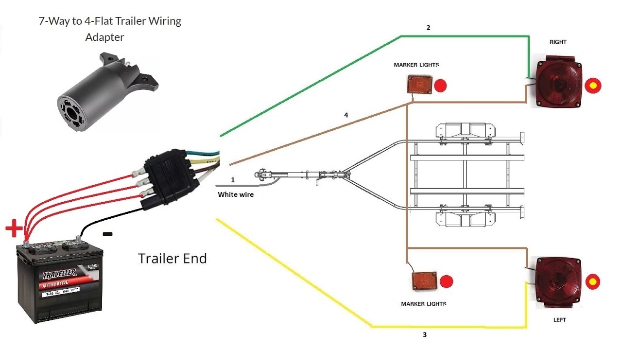
White: Ground wire Brown: Tail/running lights Yellow: Left turn/brake light Green: Right turn/brake light 18-gauge wire is the minimum recommended size for the 4-way plug. This should be used for the lights. With the ground wire, you want to use a minimum of 16-gauge. 4-pin Trailer Wiring Diagram

Trailer Lights Wiring Diagram 6 Pin Wiring Diagram And Schematic Diagram Images
Step 1: Prepare for Trailer Wiring Installation Start by making sure you have everything you need to wire your trailer, such as: A junction box to organize and secure wiring A breakaway kit in case your trailer becomes disconnected A brake controller to control trailer braking

How To Check Ground On Trailer Wiring / Trailer Light Wiring Diagram 4 Pin Database Wiring
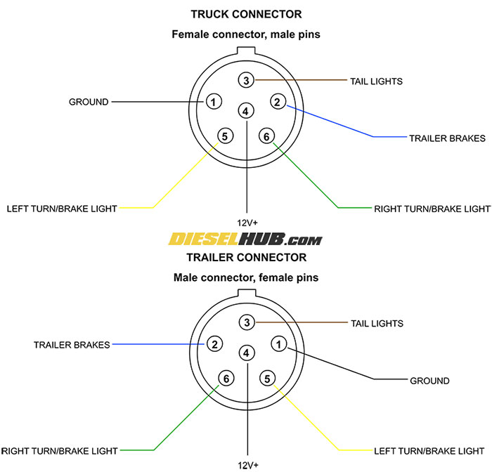
The trailer wiring diagrams listed below, should help identify any wiring issues you may have with your trailer. When shopping for trailer connectors remember that the male end is mounted on the vehicle side and the female on the trailer side. Trailer Wiring Videos 4-Way Trailer Wiring
Pin Trailer Light Wiring Diagram On Six Way Plug Get Free Image About
Trailer Wiring Connectors. Various connectors are available from four to seven pins that allow for the transfer of power for the lighting as well as auxiliary functions such as an electric trailer brake controller, backup lights, or a 12V power supply for a winch or interior trailer lights. Choose a connector that has the required number of.

How To Wire Trailer Lights 4 Way Diagram Fuse Box And Wiring Diagram
The trailer lights and wires depend on that connector, so make sure wires are soundly attached internally. Connect each wire securely, and button them all up well. Also, test, test, test all the connections. Protect the wires going from the trailer to the tow vehicle. Use a wire jacket or something else around the wires.
Trailer Light Connector Wiring
Basics: 4-Way Connector. This is the most common scenario. It has three poles for basic functions (running lights, turn signals, and brake lights) and one pin for the ground. This connector is commonly found on most light-duty trailers. On the vehicle side, there will be a female connector, while the trailer/RV harness will have a male connector.
Wiring Diagram For Trailer Lights
Wiring trailer lights can be a big task, and you want to get it right. Learn step-by-step how to wire trailer lights in no time with this tutorial! Del City.

Wiring Diagram For A Trailer Lights
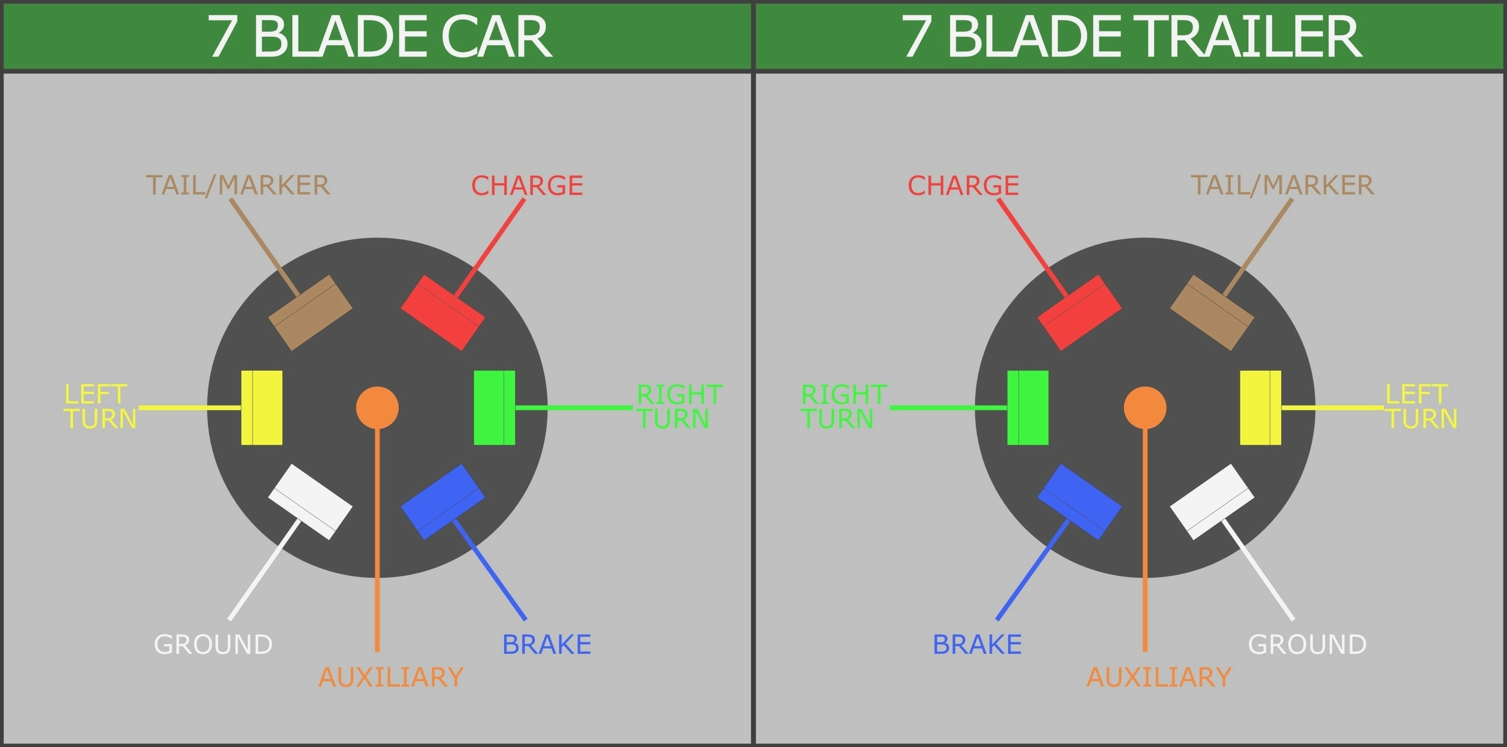
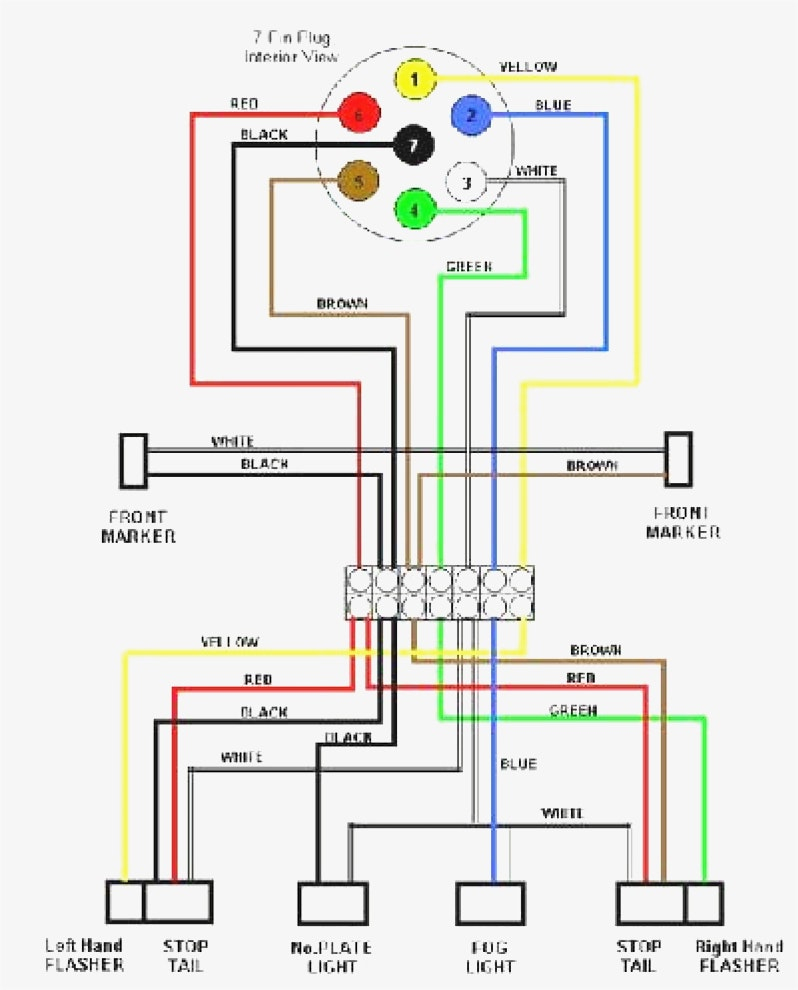
Wiring diagram for trailer 7-pin connector. Wiring diagram lighting trailer plug/socket 7-pin universal 12 volt. As the name partly gives away, the 7-pole plug consists of seven different connections. In the illustration below, these connections are indicated by different colors.
Wiring Boat Trailer Lights Diagram
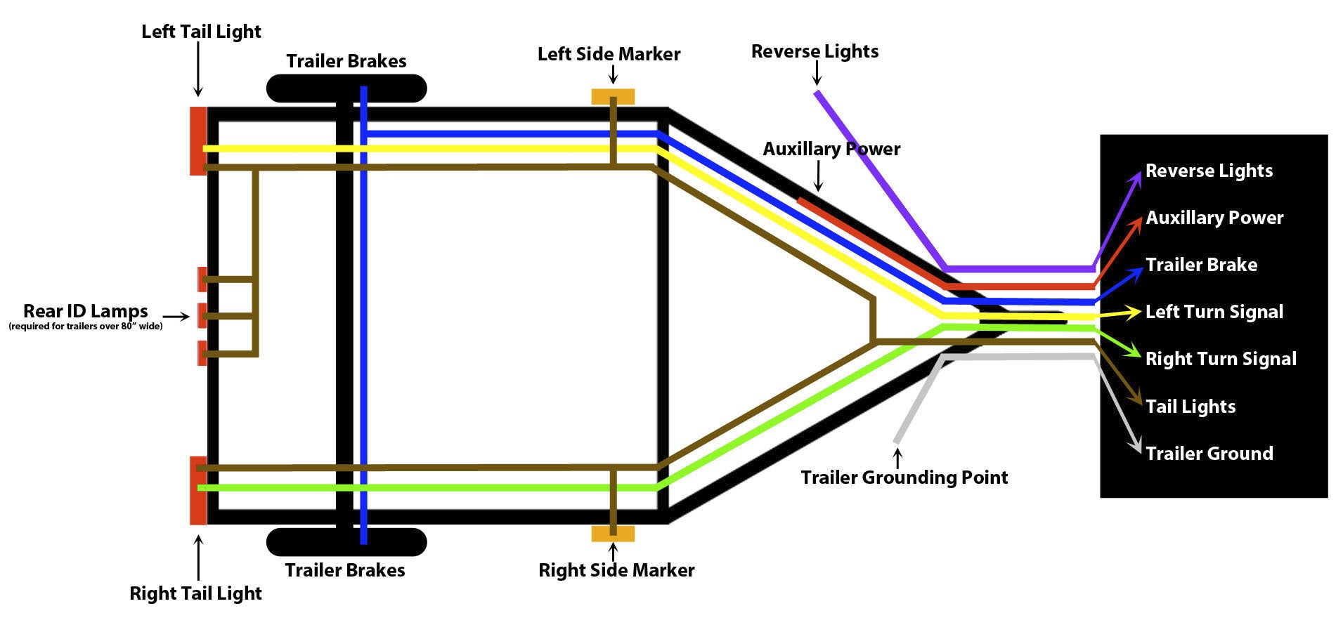
1 . White = Ground (See White Wire Notes below.) 2 . Brown = Tail Lights, Side Markers and Running Lights (See Brown Wire Notes below.) 3 . Yellow = Left Turn Signal & Left Brake Light 4 . Green = Right Turn Signal & Right Brake Light Please see the Trailer Wiring Diagram and Connector Application Chart below.

Dale Wiring Trailer Lights Wiring Diagram 5 Pin 3vdc
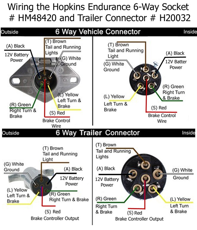
6 Way System, Rectangle Plug 3/4 inch by 1 inch 6 way rectangle connectors right turn signal (green), left turn signal (yellow), taillight (brown), ground (white). The red and blue wire can be used for brake control or auxiliary. Use on a small motorcycle trailer, snowmobile trailer or utility trailer.

7 Way Trailer Wiring Diagram Wiring Harness Diagram
RV Standard Green: Tail/running lights Yellow: Reverse Lights Brown: Right turn/brake light White: Ground wire Blue: Brake controller output Black: Battery hot lead Red: Left turn/brake light Not sure exactly what each wire does? The easiest way to figure it out is to use a circuit tester to confirm the function of each wire.

Wiring Diagram Utility Trailer Home Wiring Diagram
6-Way Connectors 6-Way connectors are available allowing the basic hookup of the three lighting functions (running, turn, and brake). The ground and two extra pins are available to provide two additional functions, typically for electric brakes and 12 volt "hot" lead. The 6-way round connectors are very common on horse trailers.
