Pressure Relief Valves An Exploration of Industrial Technology
Pressure-reducing valve Function/description : Pressure-reducing valve Detailed and simplified forms shown (X2198 and X2199) All formats: CHF 30,00 Add to basket Additional information : Detailed and simplified forms shown (X2198 and X2199). Orientation Dependent : No Formats available : DWG, EPS
check valve symbol pid Valve symbol flow control symbols piping pfd instrument drawing diagram
This device protects the pilot from over pressurization. It blocks the downstream pressure when it exceeds the adjustable limit and reopens when inlet pressure drops below the limit. The downstream pressure in the pilot tells the valve what to do next. With the set point at 150 PSI, this pilot will keep the valve open until 150 PSI is reached.
Pressure reducing valve symbol icon Royalty Free Vector
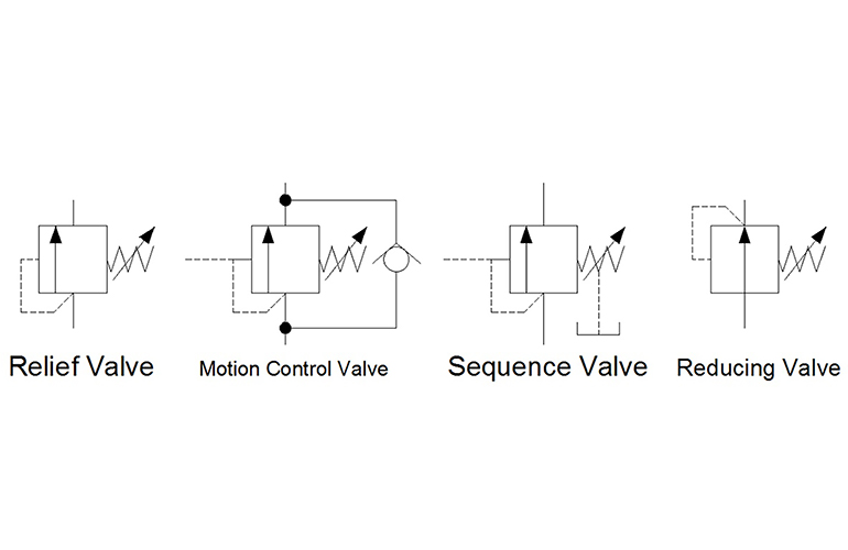
Relief valve, pressure reducing valve, and sequence valve. These pressure valves have similar schematic symbols, but the purpose and behaviour of each valve.

DIFFERENCE BETWEEN PRESSURE REDUCING VALVE AND PRESSURE RELIEF VALVE Mechanical Engineering
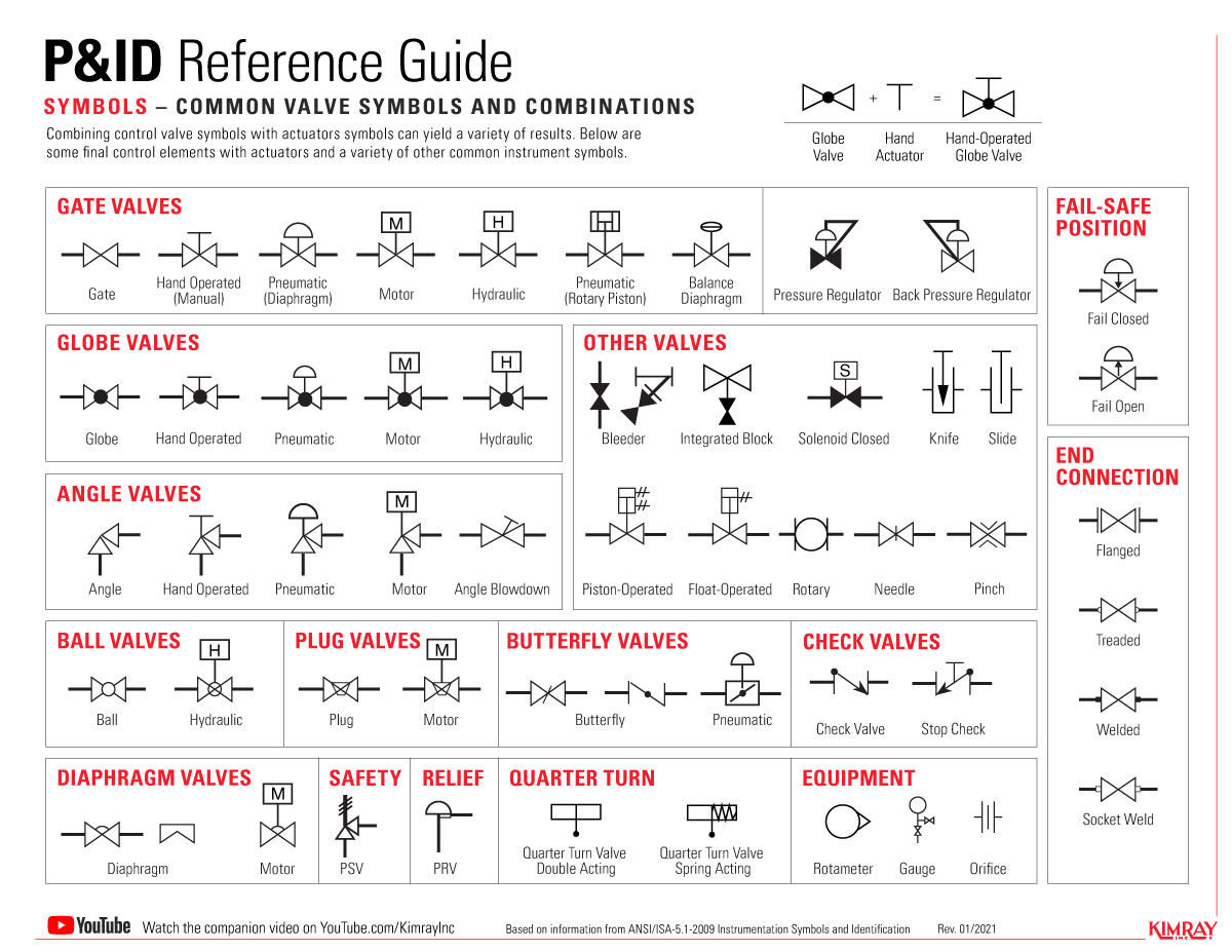
The Most Common Control Valve Symbols on a P&ID Engineers use control valve symbols to identify the type of control valve they want to specify for a given application. In this article, we will identify the most commonly used control valve symbols. What is a Piping and Instrumentation Diagram (P&ID)?
Valve Sign Symbols The Engineering Concepts
A pressure reducing valve is used for lowering and regulating water or air pressure between the upstream (inlet) and downstream (outlet) sides. We will discuss their workings in more detail a little later. In summary though, for a typical water installation: A PRV will sit in-line on a mains inlet pipe
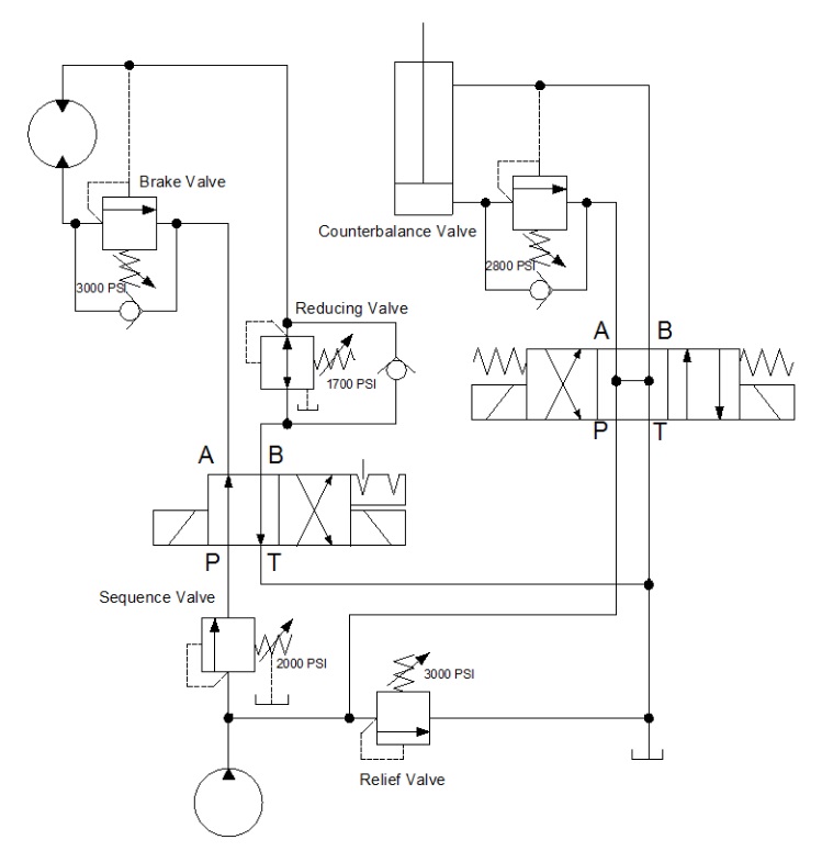
Hydraulic symbology 203 pressure valves
December 21, 2017. A piping and instrumentation diagram (P&ID) is a graphic representation of a process system that includes the piping, vessels, control valves, instrumentation, and other process components and equipment in the system. The P&ID is the primary schematic drawing used for laying out a process control system's installation.
Hydraulic symbology 203 pressure valves
IEC Symbols; JIC / NFPA Symbols; Koyo; DirectLOGIC 05/06 PLC AIO Modules; DirectLOGIC 05/06 PLC AIO Modules - Layout;. Pressure Reducing Valve, Direct, Control Oil Discharge. Reference: H1. Component: Hydraulic Pressure Reducing Valve, Direct, Control Oil Discharge. Category:
6 Pressure reducing regulator valve symbol Images, Stock Photos & Vectors Shutterstock
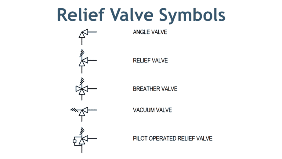
The lower symbol indicates a remote pilot operated valves. This valve will still open if the supply pressure increases, via the same dashed line, but will also open due to pressure applied on the remote line X. Note also how the drain line Y can be refereneced to a more stable drain line pressure. Learn more about pressure relief valves

check valve diagram symbols Check valve diagram ,symbol, types of check valve
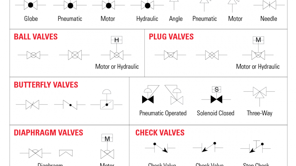
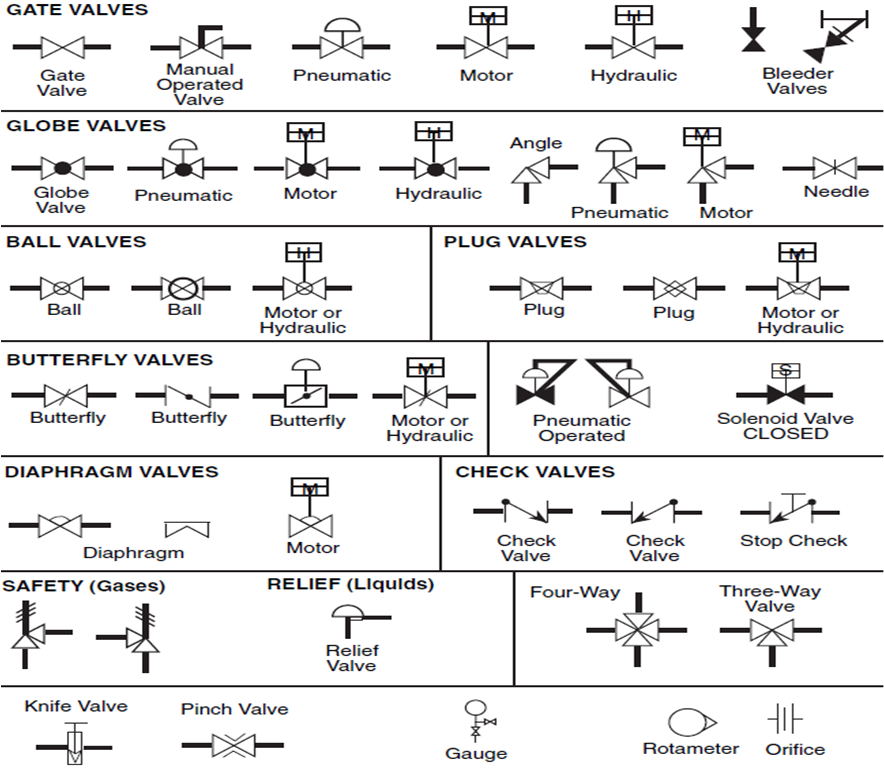
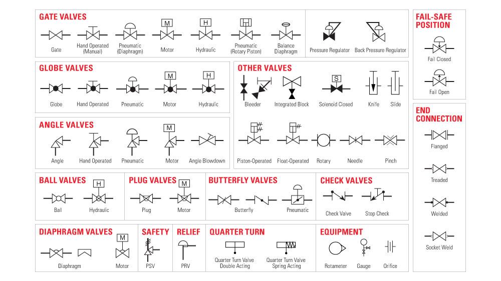
P&ID Symbols for Valves Many types of valves are required in a process plant for flow regulation or on/off purpose. Type of valve employed depends on nature of fluid, flow control required, operating pressure and temperatures as well as surround atmosphere. Here is a list of symbols for various types of valves used in process industry.

Valve Symbols in P&ID Ball Valve, Relief Valve and more
Symbols The air valve is called a regulator, but even though the name suggests that it can either increase or decrease the pressure, like the pressure reducing valve, it can only decrease the inlet pressure. In a pneumatic system, the regulator is the primary pressure control.

Symbols for Valves, Pumps and Electrical Equipment on Ship Marine World
A pressure-reducing valve is a self-operating valve that is used to reduce any excess pressure in a system. Sometimes this valve is also known as pressure reducing regulator. The basic function of pressure-reducing valves is to reduce higher pressure into lower. They are commonly used in water, steam, and oil & gas industries.
The Most Common Control Valve Symbols on a P&ID Kimray
The most common P&ID symbols are listed below: lines piping components (pipes, flanges, and fittings) valves filters instruments and instrumentation pumps compressors vessels electrical machines (motors, generators, and turbines) heat exchangers LINES P&ID SYMBOLS PIPING P&ID SYMBOLS VALVES P&ID SYMBOLS FILTERS P&ID SYMBOLS INSTRUMENTS P&ID SYMBOLS
Water Pressure Reducing Valve Symbol dreaminuyasha
There are dedicated symbols for a gate, globe, plug, and ball valves which I will explain to you in minutes. Similarly, the next two symbols are for three-way and four-way valves. It can be a plug or ball valve. The subsequent two symbols are a check valve and a stop check valve. These check valves can be swing check or lift check valves.
Pressure reducing valve symbol icon Royalty Free Vector
Last updated: May 16, 2020 Pressure reduction valve is a control valve that lowers the inlet pressure of the fluid and gives the desired pressure at the output. The pressure reduction valve maintains a constant pressure in a part of the system that operates at a pressure lower than the normal system pressure.
The Most Common Control Valve Symbols On A P&ID Kimray arnoticias.tv
5.3 Pressure Reducing Valves. NOTE: first 13 entries are REVIEW of pressure control valve family. List the 5 main types of pressure control valves. Draw their associated schematic symbols. Identify the 5 main characteristics used to classify pressure control valves. Describe the purpose of a pilot line. Describe the schematic symbol.
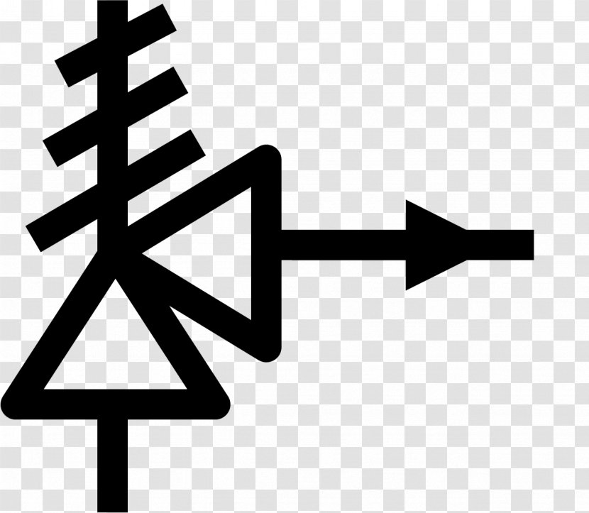
Pressure Relief Valve Symbol Basic Hydraulics Hydr 1305 Control Valves Hydr 1305 / This is
1 Scope. This part of ISO 14617 specifies graphical symbols for valves and dampers in diagrams, including symbols for general-purpose valves, those used in fluid power systems and hygienic valves used in the food and pharmaceutical industries. For the fundamental rules of creation and application of graphical symbols in diagrams, see ISO 81714-1.
